 PCB
PCB FPC
FPC Rigid-Flex
 FR-4
FR-4 HDI PCB
 Rogers High-Frequency Board
 PTFE Teflon High-Frequency Board
 Aluminum
 Copper Core
 PCB Assembly
 LED light PCBA
 Memory PCBA
 Power Supply PCBA
 New Energey PCBA
 Communication PCBA
 Industrial Control PCBA
 Medical Equipment PCBA
 Testing Service
 PCBA Testing Service
 Certification Application
 RoHS Certification Application
 REACH Certification Application
 CE Certification Application
 FCC Certification Application
 CQC Certification Application
 UL Certification Application
 Transformers, Inductors
 High Frequency Transformers
 Low Frequency Transformers
 High Power Transformers
 Conversion Transformers
 Sealed Transformers
 Ring Transformers
 Inductors
 Wires,Cables Customized
 Network Cables
 Power Cords
 Antenna Cables
 Coaxial Cables
 Net Position Indicator
 Solar AIS net position indicator
 Capacitors
 Connectors
 Diodes
 Embedded Processors & Controllers
 Digital Signal Processors (DSP/DSC)
 Microcontrollers (MCU/MPU/SOC)
 Programmable Logic Device(CPLD/FPGA)
 Communication Modules/IoT
 Resistors
 Through Hole Resistors
 Resistor Networks, Arrays
 Potentiometers,Variable Resistors
 Aluminum Case,Porcelain Tube Resistance
 Current Sense Resistors,Shunt Resistors
 Switches
 Transistors
 Power Modules
 Isolated Power Modules
 AC-DC Power Modules
 DC-AC Module(Inverter)
 RF and Wireless
Comprehensive Solution for Missing Excellon Files in Customer-Provided GERBER Files
2026-01-18
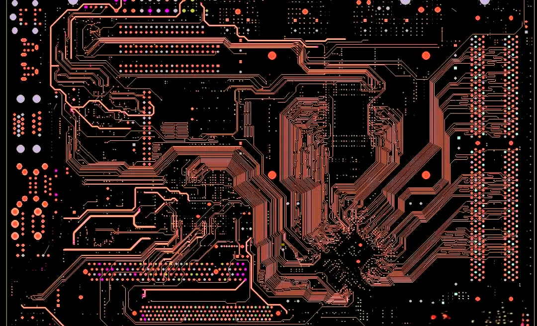
In the PCB manufacturing process, GERBER files act as the core carrier linking customer design requirements to factory production execution, containing key layer information such as PCB circuits, solder masks, silkSCReens, and copper foils. As an indispensable component of the GERBER file package, drill files (typically in Excellon format) directly define critical parameters for all through-holes, blind holes, and buried holes on thePCB—including their positions, diameters, and hole wall treatment methods—and serve as the sole execution basis for the drilling process. If the GERBER files provided by the customer lack Excellon drill files, PCB production will be directly suspended: drilling cannot be peRFormed, and subsequent processes like copper deposition, electroplating, and solder masking will also be unfeasible. This not only impairs production efficiency and delays delivery cycles but also may trigger customer complaints, increased costs, and even order disputes due to poor communication and improper handling.
For PCB manufacturing enterprises, efficiently and standardly addressing the issue of missing drill files in GERBER files is a crucial capability to ensure production continuity and enhance customer satisfaction. This article elaborates on a comprehensive solution covering problem identification, emergency handling procedures, root cause analysis methods, standardized docking mechanisms, and risk prevention and control measures. It also explains key precautions in combination with actual production scenarios, helping technical personnel and business counterparts respond quickly, handle the issue accurately, and minimize the impact on production.
I. Clarify the Problem: Core Role of Drill Files (Excellon Files) and Impact of Their Absence
Before addressing the file missing issue, it is necessary to clarify the core value of drill files and the specific impacts of their absence to avoid misdirected handling due to cognitive deviations.
The Excellon file is an industry-standard format developed by Excellon Automation, specifically designed to describe PCB drilling data, and is currently the most widely used drill file format in the PCB manufacturing industry. Its core content includes: hole position coordinates (referenced to PCB datum points), hole diameters (distinguishing between mechanical holes and laser holes), hole types (through-holes, blind holes, buried holes, positioning holes), drilling sequence, and hole wall treatment requirements (such as gold immersion, tin plating). Additionally, some Excellon files include auxiliary information like tool compensation parameters and datum point definitions to ensure drilling accuracy meets design specifications.
The absence of drill files has a global and decisive impact on PCB production, specifically reflected in the following aspects:
1. Complete Production Suspension: Drilling is a core preliminary process in PCB manufacturing, as all electrical connections and component mounting rely on drilled holes. Without drill files, drilling machines cannot obtain accurate hole position and diameter data, making it impossible to start processing. Subsequent processes such as copper deposition (to achieve hole wall conductivity), electroplating (to enhance the conductivity and wear resistance of hole walls), solder masking (to protect circuits), and silkscreen printing (to mark component positions) can only be carried out after drilling is completed, directly disrupting the production process.
2. Delivery Delays: PCB production follows a strict schedule, especially for rush orders, where each process’s timeline is precisely calculated. After drill files go missing, even with prompt communication and docking, it takes time for the customer to supplement the files and for the factory to verify their validity—usually resulting in a 1-3 day delivery delay. If the customer’s files contain errors requiring repeated revisions, the delay will be further extended, potentially leading to customer claims.
3. Increased Costs and Resource Waste: Upon receiving files, factories typically make preliminary production preparations, including material preparation, machine setup, and production scheduling. Missing drill files lead to idle prepared materials, equipment idling, and operator downtime, wasting labor, material, and time costs. If subsequent file errors occur due to communication mistakes, additional costs such as rework and scrap may also be incurred.
4. Quality Risks and Order Disputes: Blindly estimating hole positions and diameters to meet deadlines without complete drill files is highly likely to cause drilling deviations and inconsistent diameters. The final PCB will fail to meet customer design requirements and be directly scrapped. Even if files are supplemented later, material losses may result from prior misoperations, triggering customer doubts about the factory’s professionalism and even leading to disputes such as order cancellations and compensation claims.
Therefore, when facing the problem of missing drill files in GERBER files, the primary principle is "no blind production, first accurate positioning, then efficient resolution". It is strictly prohibited to start any drilling-related processing operations when files are incomplete.
II. Emergency Handling Process: Rapid Response to Minimize Production Impact
When technical personnel discover that GERBER files lack Excellon drill files during the file review phase, they should promptly address the issue following the process: "file review and confirmation → accurate customer docking → temporary plan formulation → file receipt and verification → production resumption," ensuring each step has clear operating standards and timelines.
(1) Step 1: File Review Confirmation to Rule Out Internal Errors
First, a detailed verification is required to confirm the absence of drill files, ruling out errors in internal file receiving, sorting, and storage processes to avoid misleading customers due to operational mistakes. Specific verification items include:
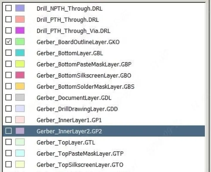
1. Comprehensive File List Sorting: A standard GERBER file package usually includes multiple layer files, including circuit layers (Top Layer, Bottom Layer), inner layers (Inner Layer 1/2, etc., for multi-layer boards), solder mask layers (Solder Mask Top/Bottom), silkscreen layers (Silkscreen Top/Bottom), stencil layers (Stencil Top/Bottom, if required), drill files (Excellon File, usually named "Drill," "Excellon," or with a ".drl" suffix), drill drawings (Drill Drawing, with a ".drd" suffix, used to assist in verifying drilling information), board outline layer (Board Outline), and datum point files (Fixture). Technical personnel should check each file individually to confirm the presence of files with a ".drl" suffix or containing the keywords "Drill" or "Excellon" in their names.
2. File Naming and Format Inspection: Some customers may confuse drill files with other layer files due to non-standard naming—for example, mistakenly naming "Drill.drl" as "Drill.gbr." Simultaneously, confirm that the file format is standard Excellon, avoiding confusing drill drawings (.drd) with drill files. Drill drawings are only visual reference diagrams; they do not contain coordinate and diameter data recognizable by drilling machines and cannot replace Excellon files.
3. Compressed Package and Transmission Record Verification: If the customer transmits files via email, cloud disk, or other methods, check that the compressed package is fully decompressed and that there are no hidden files or subfolders (some customers store drill files separately in a "Drill" subfolder). Additionally, verify file transmission records to confirm the number of files sent by the customer matches the number received, ruling out file loss during transmission.
4. Cross-Departmental Mutual Verification: If no drill files are found in the preliminary verification, arrange for another technical personnel to repeat the process to avoid individual oversights. Simultaneously, coordinate with the business department to confirm whether the customer provided special instructions when placing the order, such as "supplementing drill files later" or "drilling data is included in other files."
After the above verification, if the absence of drill files is confirmed, immediately initiate customer docking and document the verification process and results to provide a basis for subsequent communication.

(2) Step 2: Accurate Customer Docking to Clarify Requirements and Time Nodes
The core goal of customer docking is to quickly obtain complete, valid Excellon drill files while clarifying the customer’s design requirements and time expectations, avoiding delayed or non-compliant file supplementation due to ambiguous communication. The docking process should adhere to the principles of "accuracy, professionalism, and efficiency," with specific operations as follows:
1. Initiate Timely Communication and Explain the Core Issue: Within one hour of confirming the missing files, contact the customer’s counterpart via phone, email, instant messaging, or other means to clearly state the problem: "The GERBER file package provided by your company lacks standard Excellon drill files (.drl format). This file is the sole execution basis for the PCB drilling process; production is currently halted and can only resume after your company supplements the files." Avoid vague expressions such as "incomplete files" or "missing drilling-related files" to ensure the customer fully understands the issue.
2. Provide File List References to Guide Supplementation: To help the customer quickly locate the required files, send a standard GERBER file list marking the name, format (.drl), and naming conventions (e.g., "PCB_NAME_Drill.drl") of the missing drill files. Additionally, explain the core content required in the drill files: hole position coordinates, diameters, types (through-holes/blind holes/buried holes), datum point correspondence, and tool compensation parameters (if applicable). For non-professional designers, provide sample files to reduce the difficulty of file supplementation.
3. Clarify Timelines and Delivery Methods: Based on the factory’s production schedule, inform the customer that "to meet the original delivery deadline, drill files must be supplemented within X hours," and negotiate the latest supplementation time to avoid delays due to customer procrastination. Specify preferred file delivery channels—prioritizing high-speed, stable options such as enterprise cloud disks or dedicated file transfer tools—to avoid transmitting large files via instant messaging platforms like WeChat (which are prone to compression distortion and file corruption). Additionally, require the customer to send a confirmation email after supplementing the files for documentation purposes.
4. Proactively Address Potential Customer Questions and Provide Professional Support: Some customers may not know how to export Excellon files or have questions about file formats due to design process issues. In such cases, take the initiative to provide technical support, for example:
- Explain Excellon file export methods for common design software (e.g., Altium Designer: Execute "File→Fabrication Outputs→NC Drill Files," select Excellon format, and check parameters such as "Include Hole Sizes" and "Use Absolute Coordinates"; PADS: Execute "File→CAM→NC Drill," set the unit and coordinate origin, then export);
- Remind the customer to ensure unit consistency when exporting files (preferably millimeters or inches, matching other GERBER layers), align the coordinate origin with the board outline’s datum points (to avoid hole position deviation), and clarify layer information for blind/buried holes (e.g., "blind holes from Top Layer to Inner Layer 1");
- If the customer cannot export the files independently, negotiate for the factory’s technical personnel to assist—requiring the customer to provide design source files (e.g., .pcb, .sch formats) and sign a non-disclosure agreement (NDA) to protect the confidentiality of their design intellectual property.
5. Confirm Special Design Requirements to Avoid Subsequent Disputes: During docking, simultaneously confirm the customer’s special drilling requirements, such as hole wall treatment (gold immersion, tin plating, hot air solder leveling), hole diameter tolerance (e.g., ±0.05mm), positioning hole locations, and no-drilling zones. Document these requirements in communication minutes and verify them alongside the supplemented drill files later to ensure production aligns with customer needs.
6. Synchronize Communication Progress and Feedback Issues Promptly: If the customer encounters difficulties supplementing files (e.g., export failures, format errors), proactively follow up and provide necessary technical guidance. If the customer cannot meet the agreed supplementation deadline, promptly inform the factory’s production department to adjust the schedule and negotiate a new delivery cycle with the customer to align expectations.
(3) Step 3: Formulate Temporary Plans to Reduce Production Delay Impact
While waiting for the customer to supplement drill files, formulate temporary production plans to allocate resources reasonably and minimize the impact of delays. Specific measures include:
1. Adjust Production Scheduling and Prioritize Other Orders: Immediately coordinate with the production planning department to suspend drilling for the affected order, reallocating idle drilling machines and operators to other orders with complete files to avoid equipment and labor idling. Simultaneously, re-plan the affected order’s production cycle, reserving time for file verification and machine setup to ensure rapid production resumption once drill files are received.
2. Complete Preliminary Preparation Work in Advance: Without relying on drill files, advance preparations for other preliminary processes, such as verifying the completeness and accuracy of other GERBER layers (ensuring circuits, solder masks, and silkscreens are clear and the board outline is defined), material preparation (cutting copper-clad laminates, preparing solder mask agents and silkscreen inks), debugging drilling machine parameters (e.g., rotation speed and feed rate, preset based on common hole diameters), and manufacturing datum point positioning jigs. Completing these tasks in advance allows for immediate transition to drilling once files are available, shortening the overall production cycle.
3. Establish a Green Channel for File Receipt: Assign dedicated personnel to handle the customer’s supplemented files, ensuring preliminary verification (format, size, and naming compliance) is conducted immediately upon receipt to avoid delays from unattended files. Additionally, prepare file verification tools (e.g., GerberView, CAM350) to initiate the verification process promptly after files are received.
(4) Step 4: File Receipt and Comprehensive Verification to Ensure Compliance with Production Requirements
After the customer supplements the drill files, conduct comprehensive, rigorous verification to confirm file validity and data accuracy, preventing quality issues such as drilling deviations and inconsistent diameters caused by file errors. The verification process must cover the following core points:
1. Format and Completeness Verification: First, confirm the file is in standard Excellon format (.drl), undamaged, and free of garbled characters (open the file with Notepad to check for clear coordinate and diameter data, e.g., "X10000Y20000T1C," where T1 denotes the tool number and C denotes the drilling command). Simultaneously, verify that the file contains all drilling data—if the customer’s design includes multiple hole diameters or types (e.g., mechanical + laser holes, through-holes + blind/buried holes), confirm corresponding Excellon files are provided separately (some customers export different drilling data types independently).
2. Unit and Coordinate Origin Verification: Ensure the drill file’s unit matches other GERBER layers (millimeters/inches). If units are inconsistent, contact the customer to confirm and correct, as unit errors can cause significant deviations (e.g., mistaking inches for millimeters enlarges diameters by 25.4 times, rendering the PCB unusable). Additionally, verify the coordinate origin aligns with the board outline and datum points—overlay the drill file with the board outline layer using CAM software to ensure holes are within the PCB boundary, preventing drilling beyond the board edge.
3. Hole Diameter and Type Verification: Use CAM software to review the drill file’s diameter list, cross-verifying with customer-confirmed requirements and component pin sizes in the BOM (Bill of Materials) to ensure accuracy. For example, through-hole diameters for through-hole components should be 0.1-0.2mm larger than pin diameters to facilitate assembly. For blind/buried holes, confirm layer information (e.g., blind hole start/end layers) matches the PCB layer design, preventing poor hole wall conduction due to incorrect layer division.
4. Hole Position Accuracy Verification: Overlay the drill file with the circuit layer to confirm drilling positions align with circuit pads and vias, avoiding poor conduction between pads and hole walls due to deviation. Focus on dense hole areas (e.g., BGA packaging zones) to ensure hole spacing meets design requirements without overlap or offset.
5. Special Requirement Verification: For customer-specified drilling requirements (e.g., separate positioning hole drilling, hole wall gold immersion thickness, no-drilling zones), verify compliance one by one. Examples include confirming positioning hole diameter/position match requirements, no drilling data exists in no-drilling zones, and blind/buried hole wall treatment requirements are clearly noted in the file.
If errors are found during verification (e.g., inconsistent diameters, position deviations, incorrect layer division), immediately take screenshots to mark issues, feedback to the customer, and request correction and resubmission. Once verification passes, complete a "GERBER File Verification Report" stating "the drill file is valid and approved for production," and distribute it to the production department to initiate drilling.
(5) Step 5: Production Resumption and Process Control to Ensure Stable Quality
After drill file verification, quickly resume production and strengthen process control to avoid quality oversights in subsequent processes due to prior delays. Specific measures include:
1. Synchronize with Production and Start Drilling: Distribute the verified drill file, "File Verification Report," and customer special requirements to the drilling workshop, clarifying production priority (for rush orders, prioritize drilling). Arrange technical personnel to provide on-site guidance, assisting operators in importing the drill file into the drilling machine and verifying parameters such as tool number, diameter, and coordinate origin to ensure alignment between equipment settings and file data.
2. First Article Inspection (FAI) Confirmation: After initiating drilling, produce a first article PCB and inspect drilling accuracy using equipment such as Automatic Optical Inspection (AOI) and microscopes. Check that hole position deviation is within the allowable range (usually ±0.02mm), diameters meet requirements, hole walls are smooth without burrs, and blind/buried holes conduct normally. Mass production may only begin after FAI approval. If the first article fails, immediately stop production to investigate causes (e.g., file import errors, equipment parameter deviations), correct issues, and re-produce the first article.
3. In-Process Inspection During Mass Production: Conduct regular sampling inspections during mass drilling, focusing on diameter consistency, position accuracy, and hole wall quality to prevent fluctuations caused by equipment wear or tool depletion. Record production data (e.g., drilling speed, tool lifespan) for subsequent quality traceability.
4. Synchronize Production Progress with the Customer: After production resumes, promptly update the customer on progress, informing them "the drill file has been verified, production has resumed, drilling is expected to complete at XX time, and the overall delivery cycle will proceed as scheduled for XX time" to alleviate anxiety and enhance trust.
III. Root Cause Analysis: Why Do Drill Files Go Missing?
Beyond customer oversights during design and file export, missing drill files may also stem from imperfect factory docking processes and file review standards. Root cause analysis enables targeted improvements to reduce recurrence. Common root causes are categorized below:
(1) Customer-Side Causes
1. Designer Operational Oversights: Customer designers may omit drill file export or mistakenly send drill drawings as drill files when generating GERBER packages. Some non-professional designers lack understanding of GERBER package composition, mistakenly believing only circuit and solder mask layers are required.
2. Non-Standard File Naming and Sorting: Non-standard naming may cause customers to confuse drill files with other layers, or failure to sort files by category leads to omissions during transmission. Some customers store drill files in separate folders and forget to include them when sending.
3. File Format Misunderstandings: Customers may send non-standard drilling data files (e.g., custom formats, CAD-exported text files) as Excellon files, or believe "design source files (.pcb) can replace drill files," ignoring the factory’s requirement for standard Excellon formats for production.
4. Internal Customer Communication Errors: Poor internal coordination between the customer’s design and procurement departments may result in procurement sending files without confirming drill file completion with design. Alternatively, customers may mistakenly believe "drilling data is included in the board outline or circuit layers" and omit separate drill files.
(2) Factory-Side Causes
1. Imperfect File Review Processes: Factories without standardized GERBER file review checklists may have technical personnel focus solely on core layers (circuits, solder masks) and overlook drill file verification. Overly simplified, single-person review processes also increase the risk of oversights.
2. Inaccurate Business Docking: Business personnel may fail to clearly communicate GERBER package requirements (including drill file format, naming, and content) when undertaking orders, only instructing customers to "provide GERBER files." This ambiguity leads to customer misunderstandings and subsequent file omissions or errors.
3. Insufficient Technical Support: Failure to provide non-professional customers with standardized export guides and sample files may cause difficulties in drill file export or result in non-compliant files. Delayed responses to customer file issues further prolong problem resolution.
4. Non-Standard File Transmission and Storage: Lack of dedicated file transmission channels leads to customers using informal methods, increasing the risk of file loss or corruption. Failure to store files by order category hinders quick location during subsequent verification.
IV. Establish Standardized Processes: Prevent Drill File Missing from the Source
Establishing standardized file docking, review, and control processes reduces missing drill file incidents at the source, improving production efficiency and customer satisfaction. Process improvements should focus on the following areas:
(1) Formulate Standardized File Requirements and Inform Customers in Advance
1. Develop a "GERBER File Submission Guide": Explicitly require customers to include standard Excellon drill files (.drl format) in their GERBER packages. Detail drill file naming conventions, format requirements, and core content (positions, diameters, types, layer information, etc.). Provide export steps and parameter suggestions for common design software (Altium Designer, PADS, Cadence), accompanied by sample files and error case comparisons.
2. Clarify File Requirements During Order Docking: Business personnel must share the "GERBER File Submission Guide" with customers when finalizing orders, explaining requirements in detail, emphasizing drill file importance, and confirming customer understanding and compliance. For non-professional customers, proactively offer file export and verification assistance to prevent operational errors.
3. Sign a File Confirmation Agreement: Include a "file confirmation clause" in order contracts, specifying that customers must provide complete, valid GERBER files (including Excellon drill files). Production will commence only after factory verification. Clarify that customers bear responsibility for production delays or rework caused by missing or incorrect files (or resolve via negotiation) to avoid disputes.
(2) Improve the File Review Process and Establish a Dual Verification Mechanism
1. Develop a "GERBER File Review Checklist": Make drill file verification a core item, specifying review criteria (existence, standard format, unit consistency, accurate diameters/positions, special requirement compliance). Technical personnel must check each item to ensure no omissions.
2. Implement a Dual Review System: All GERBER files require cross-review by two technical personnel. The first reviewer completes a preliminary check and documents comments; the second reviewer conducts a re-verification. Only after confirmation and signing of the "File Verification Report" can files be released to production. Any issues discovered must trigger immediate customer docking and documentation.
3. Adopt Automated Review Tools: Deploy professional GERBER review software (e.g., CAM350, Valor NPI) to automatically detect file completeness (missing drill files/layers), format errors, unit inconsistencies, and position deviations. This improves review efficiency and accuracy, reducing manual oversights.
(3) Optimize File Transmission and Storage Management to Ensure File Security
1. Establish Dedicated File Transmission Channels: Provide customers with factory-exclusive platforms (e.g., enterprise cloud disks, FTP servers), specifying transmission paths and naming rules to avoid informal channels. Set up file receipt notifications to ensure technical personnel are alerted immediately upon file arrival.
2. Standardize File Storage: Create order-numbered folders for file storage, centralizing GERBER files, review reports, communication records, and supplementary files. Classify files as "original," "verified," and "supplementary" for easy verification and traceability. Regularly back up files to prevent loss or corruption.
(4) Strengthen Customer Service and Technical Support to Improve Docking Efficiency
1. Assign Exclusive Customer File Docking Personnel: Allocate dedicated technical contacts to key customers and non-professional clients, overseeing the entire process from file receipt and review to communication and technical guidance. This avoids information errors from frequent contact changes.
2. Early Involvement in Customer Design: For complex PCB orders (e.g., multi-layer, blind/buried hole boards), proactively provide design-phase technical support. Guide customers in optimizing drilling layouts and selecting diameters, and remind them of drill file export precautions to prevent issues at the source.
3. Conduct Regular Customer Training: Organize online/offline training for long-term and non-professional customers, covering standard GERBER file production, export, and submission processes. Focus on Excellon drill file export methods and common error avoidance to improve submission standardization.
V. Risk Prevention and Emergency Contingency Plans
While standardized processes significantly reduce missing drill file incidents, risk prevention measures and emergency contingency plans are essential to address extreme scenarios (e.g., customer inability to supplement files, severe delays, uncorrectable errors) and minimize losses.
(1) Risk Prevention Measures
1. Pre-Assess Customer Risks: For new or non-professional customers, assess file submission risks during order negotiation. Require preliminary file drafts for review and sign formal contracts only after confirming completeness and standardization, avoiding production stagnation.
2. Reserve Buffer Time: Allocate 1-2 days of buffer time in production schedules for file review and problem resolution—especially for rush orders—to mitigate delays from missing or incorrect files.
3. Establish File Backup Mechanisms: Retain drill file templates and design specifications for long-term customers. If customers encounter file issues and cannot supplement promptly, use historical templates to provide reference solutions and assist in quick corrections.
(2) Emergency Contingency Plans
1. Customer Inability to Export Excellon Files: If customer designers cannot export standard Excellon files independently, factory technical personnel may assist—provided the customer supplies design source files (.pcb, .sch) and signs an NDA. After export, verify key parameters (diameters, positions, types) with the customer before production use.
2. Missed Supplementation Deadlines: If customers cannot supplement files on time due to design adjustments or personnel changes, negotiate a new delivery cycle and adjust production schedules. If the original deadline must be maintained, evaluate emergency measures (e.g., dedicated personnel to follow up, process optimization to shorten timelines) and clarify customer responsibility for emergency costs.
3. Uncorrectable File Errors: If supplemented drill files have critical errors (e.g., large-scale position deviations, incorrect layer information) that cannot be fixed promptly, advise the customer to suspend production, re-optimize the design, and re-export. If the customer insists on using incorrect files, require a signed "Risk Notification Letter" clarifying potential quality issues (e.g., PCB scrapping, assembly failure) and customer liability.
VI. Summary
Missing Excellon drill files in customer-provided GERBER packages are a common issue in PCB production, with direct impacts on efficiency, delivery, and customer satisfaction. The core solution lies in "rapid response, accurate docking, strict verification, and standardized processes"—minimizing delays by promptly securing valid files, verifying rigorously, and resuming production quickly. Standardized docking, review, and control processes prevent incidents at the source, enhancing overall operational efficiency and service quality.
For PCB manufacturers, file management is a critical component of production control. Continuous process optimization and enhanced technical support not only resolve issues like missing drill files but also strengthen customer trust and core competitiveness. Additionally, multi-party collaboration (business, technical, production, and customer teams) is essential to establish efficient problem-solving and risk mitigation mechanisms.