 PCB
PCB FPC
FPC Rigid-Flex
 FR-4
FR-4 HDI PCB
 Rogers High-Frequency Board
 PTFE Teflon High-Frequency Board
 Aluminum
 Copper Core
 PCB Assembly
 LED light PCBA
 Memory PCBA
 Power Supply PCBA
 New Energey PCBA
 Communication PCBA
 Industrial Control PCBA
 Medical Equipment PCBA
 Testing Service
 PCBA Testing Service
 Certification Application
 RoHS Certification Application
 REACH Certification Application
 CE Certification Application
 FCC Certification Application
 CQC Certification Application
 UL Certification Application
 Transformers, Inductors
 High Frequency Transformers
 Low Frequency Transformers
 High Power Transformers
 Conversion Transformers
 Sealed Transformers
 Ring Transformers
 Inductors
 Wires,Cables Customized
 Network Cables
 Power Cords
 Antenna Cables
 Coaxial Cables
 Net Position Indicator
 Solar AIS net position indicator
 Capacitors
 Connectors
 Diodes
 Embedded Processors & Controllers
 Digital Signal Processors (DSP/DSC)
 Microcontrollers (MCU/MPU/SOC)
 Programmable Logic Device(CPLD/FPGA)
 Communication Modules/IoT
 Resistors
 Through Hole Resistors
 Resistor Networks, Arrays
 Potentiometers,Variable Resistors
 Aluminum Case,Porcelain Tube Resistance
 Current Sense Resistors,Shunt Resistors
 Switches
 Transistors
 Power Modules
 Isolated Power Modules
 AC-DC Power Modules
 DC-AC Module(Inverter)
 RF and Wireless
Hand Soldering Through-Hole Components: Optimal Iron Temperature and Dwell Time Guidelines
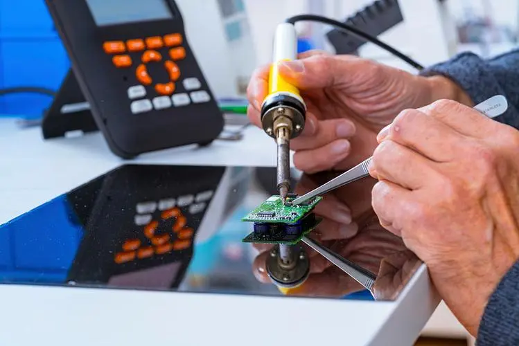
Hand soldering through-hole components—such as bipolar junction transistors (BJTs), electrolytic capacitors, diodes, and resistors—is a fundamental skill in electronics assembly, prototyping, and repair. While seemingly straightforward, achieving reliable, high-quality solder joints requires precise control of two critical parameters:soldering iron tip temperature and dwell time(the duration the iron is in contact with the joint). Deviations can lead to cold joints, thermal damage, lifted pads, or degraded component peRFormance.
This article details the recommended settings—iron temperature between 320°C and 350°C and dwell time of 2–3 seconds—and explains the engineering rationale behind these values for typical through-hole components.
1. Why Temperature Matters: The 320–350°C Sweet Spot
a) Solder Alloy Melting Characteristics
Most electronics use Sn63/Pb37 (tin-lead) or SAC305 (lead-free: Sn96.5/Ag3.0/Cu0.5) solder:
- Sn63/Pb37: Melts at 183°C (eutectic)
- SAC305: Melts at ~217–220°C
However, the iron tip must be significantly hotter than the melting point to:
- Compensate for heat loss to leads, pads, and ambient air
- Ensure rapid wetting and intermetallic bond formation
A tip temperature of 320–350°C provides sufficient thermal energy to melt solder quickly while minimizing thermal stress.
b) Component Thermal Limits
Many through-hole components have maximum allowable lead temperatures:
- Transistors (e.g., TO-92, TO-220): Typically rated for ≤ 300–350°C at the lead for ≤ 10 seconds during soldering (per JEDEC J-STD-020).
- Electrolytic capacitors: Sensitive to heat; prolonged exposure > 300°C can dry out electrolyte or rupture seals.
- Plastic-bodied parts: May deform above 350°C.
Operating at 320–350°C ensures the lead reaches soldering temperature quickly without exceeding safe internal limits—provided dwell time is controlled.
c) Oxidation and Tip Life
Temperatures above 370°C accelerate:
- Oxidation of the soldering iron tip (reducing heat transfer)
- Flux burn-off before it can clean the surfaces
- Degradation of rosin or no-clean fluxes
Thus, 350°C is generally the upper practical limit for hand soldering.
2. Why Dwell Time Must Be 2–3 Seconds
The dwell time—how long the iron contacts the joint—is equally critical:
a) Too Short (<1–2 s):
- Insufficient heat transfer to the pad and lead
- Solder doesn’t fully wet the surfaces → cold or grainy joints
- Poor intermetallic compound (IMC) formation → weak mechanical/electrical connection
b) Too Long (>3–4 s):
- Excessive heat conducts into the component body
- In transistors: Can alter doping profiles or damage semiconductor junctions
- In capacitors: May vaporize electrolyte, reduce capacitance, or cause venting
- PCB delamination or pad lifting, especially on single-sided or low-Tg boards
- Solder oxidizes, leading to dull, brittle joints
c) The 2–3 Second Window
At 320–350°C, 2–3 seconds is typically enough to:
- Heat the copper pad and component lead to ~250–280°C
- Melt fresh solder and allow it to flow via capillary action
- Enable proper flux activation and oxide removal
- Form a shiny, concave fillet with strong adhesion
Note: This assumes a standard 60W temperature-controlled iron with a clean, tinned chisel or conical tip (1.6–2.4 mm width).
3. Practical Technique for Consistent Results
To achieve reliable joints within these parameters:
- Pre-tin the tip: Apply a small amount of solder to ensure good thermal contact.
- Simultaneously heat pad and lead: Touch the iron to both for 1–1.5 seconds.
- Apply solder wire opposite the iron: Feed solder until it flows smoothly around the lead (1–1.5 seconds).
- Remove solder first, then iron: Hold the joint still until solidified (~1 second).
- Total contact time: Should not exceed 3 seconds.
Use a timer or metronome app during training to build muscle memory.
4. Special Considerations
| Component Type | Recommendation Adjustment |
|---|---|
| Large ground pins / metal cans | Increase dwell to 3–4 s or preheat board |
| Heat-sensitive parts (e.g., film caps) | Use 320°C, ≤2 s, add heatsink clip |
| Lead-free solder | Use 340–360°C, but keep time ≤3 s |
| Multi-layer or thick PCBs | May require 350°C due to higher thermal mass |
For reliable hand soldering of standard through-hole components like transistors and capacitors, a soldering iron temperature of 320–350°C combined with a controlled dwell time of 2–3 seconds strikes the optimal balance between:
- Rapid, complete wetting
- Minimal thermal damage
- Strong metallurgical bonding