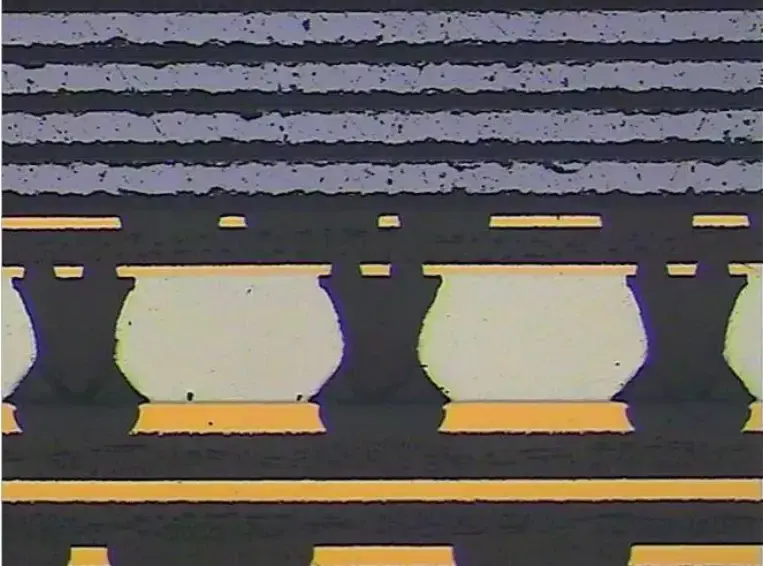
 PCB
PCB FPC
FPC Rigid-Flex
 FR-4
FR-4 HDI PCB
 Rogers High-Frequency Board
 PTFE Teflon High-Frequency Board
 Aluminum
 Copper Core
 PCB Assembly
 LED light PCBA
 Memory PCBA
 Power Supply PCBA
 New Energey PCBA
 Communication PCBA
 Industrial Control PCBA
 Medical Equipment PCBA
 Testing Service
 PCBA Testing Service
 Certification Application
 RoHS Certification Application
 REACH Certification Application
 CE Certification Application
 FCC Certification Application
 CQC Certification Application
 UL Certification Application
 Transformers, Inductors
 High Frequency Transformers
 Low Frequency Transformers
 High Power Transformers
 Conversion Transformers
 Sealed Transformers
 Ring Transformers
 Inductors
 Wires,Cables Customized
 Network Cables
 Power Cords
 Antenna Cables
 Coaxial Cables
 Net Position Indicator
 Solar AIS net position indicator
 Capacitors
 Connectors
 Diodes
 Embedded Processors & Controllers
 Digital Signal Processors (DSP/DSC)
 Microcontrollers (MCU/MPU/SOC)
 Programmable Logic Device(CPLD/FPGA)
 Communication Modules/IoT
 Resistors
 Through Hole Resistors
 Resistor Networks, Arrays
 Potentiometers,Variable Resistors
 Aluminum Case,Porcelain Tube Resistance
 Current Sense Resistors,Shunt Resistors
 Switches
 Transistors
 Power Modules
 Isolated Power Modules
 AC-DC Power Modules
 DC-AC Module(Inverter)
 RF and Wireless
How to monitor the fatigue cracks of BGA solder joints in real time through acoustic emission technology?
Real-Time Monitoring of BGA Solder Joint Fatigue Cracks via AcoustIC Emission Technology
1. Principles and Applicability of Acoustic Emission (AE)
AE technology detects high-frequency elastic stress waves (20 kHz–1 MHz) released by internal material deformation or damage. Fatigue cracks in BGA solder joints under thermal cycling or mechanical stress generate transient AE signals correlated with crack propagation, enabling real-time, non-destructive, and high-sensitivity monitoring.

2. AE Signal Characteristics of BGA Fatigue Cracks
-
Signal Types:
-
Burst Signals: Short, high-amplitude pulses (microsecond duration) from rapid crack growth, with energy concentrated at 100–300 kHz.
-
Continuous Signals: Low-amplitude sustained signals from slow crack growth or friction, below 100 kHz.
-
-
Key Parameters:
-
Amplitude: Reflects crack energy; sudden increases indicate unstable propagation.
-
Count Rate: Events per unit time, proportional to crack growth rate.
-
Energy: Quantifies cumulative damage via signal envelope integration.
-
3. Real-Time Monitoring System Architecture
(1) Sensor Placement and Coupling Optimization
-
Sensor Type: Broadband piezoelectric sensors (e.g., PAC R15α, 50–400 kHz).
-
Installation:
-
Direct coupling on PCB backside near BGA with impedance-matched grease.
-
Array layout with Time Difference of Arrival (TDOA) for crack localization (±5 mm accuracy).
-
(2) Signal Acquisition and Noise Reduction
-
Hardware:
-
High-sampling AE cards (≥5 MS/s, ≥16-bit resolution, ≥80 dB dynamic range).
-
40–60 dB preamps with 20–500 kHz bandpass Filters.
-
-
Software:
-
Wavelet transforms to isolate AE signals from noise.
-
SVM/CNN classifiers to differentiate cracks from false events.
-
(3) Damage Assessment and Alert Logic
-
Feature Extraction: Real-time calculation of amplitude, rise time, RA value, etc.
-
Damage Model: Relates crack growth rate (da/dN) to AE parameters (e.g., cumulative energy).
-
Alerts:
-
Primary Warning: Trigger manual inspection if count rate exceeds baseline by 200%.
-
Critical Shutdown: Halt production if amplitude >80 dB and energy slope surges.
-
4. Validation and Application Scenarios
-
Accelerated Thermal Cycling:
-
Apply -40°C↔125°C cycles (per JEDEC JESD22-A104) while monitoring AE signals.
-
Validate against X-ray/dye penetrant results (≥95% detection rate).
-
-
In-Line Monitoring:
-
Integrate AE systems at ICT or burn-in stations for real-time health checks.
-
5. Challenges and Solutions
-
Challenge 1: Environmental Noise
-
Solution: Adaptive Noise Cancellation (ANC) with reference sensors.
-
-
Challenge 2: Signal Overlap from Multiple Joints
-
Solution: Sensor arrays + beamforming for SNR enhancement.
-
-
Challenge 3: Low Sensitivity to Early Micro-Cracks
-
Solution: Resonant sensors + frequency band optimization (200–300 kHz).
-
6. Advantages and Limitations
-
Advantages:
-
Real-time monitoring without downtime;
-
Detects hidden defects (e.g., head-in-pillow);
-
Enables predictive maintenance.
-
-
Limitations:
-
Requires precise sensor positioning;
-
False alarms in noisy environments need optimization.
-