 PCB
PCB FPC
FPC Rigid-Flex
 FR-4
FR-4 HDI PCB
 Rogers High-Frequency Board
 PTFE Teflon High-Frequency Board
 Aluminum
 Copper Core
 PCB Assembly
 LED light PCBA
 Memory PCBA
 Power Supply PCBA
 New Energey PCBA
 Communication PCBA
 Industrial Control PCBA
 Medical Equipment PCBA
 Testing Service
 PCBA Testing Service
 Certification Application
 RoHS Certification Application
 REACH Certification Application
 CE Certification Application
 FCC Certification Application
 CQC Certification Application
 UL Certification Application
 Transformers, Inductors
 High Frequency Transformers
 Low Frequency Transformers
 High Power Transformers
 Conversion Transformers
 Sealed Transformers
 Ring Transformers
 Inductors
 Wires,Cables Customized
 Network Cables
 Power Cords
 Antenna Cables
 Coaxial Cables
 Net Position Indicator
 Solar AIS net position indicator
 Capacitors
 Connectors
 Diodes
 Embedded Processors & Controllers
 Digital Signal Processors (DSP/DSC)
 Microcontrollers (MCU/MPU/SOC)
 Programmable Logic Device(CPLD/FPGA)
 Communication Modules/IoT
 Resistors
 Through Hole Resistors
 Resistor Networks, Arrays
 Potentiometers,Variable Resistors
 Aluminum Case,Porcelain Tube Resistance
 Current Sense Resistors,Shunt Resistors
 Switches
 Transistors
 Power Modules
 Isolated Power Modules
 AC-DC Power Modules
 DC-AC Module(Inverter)
 RF and Wireless
Measurement of the Accuracy of a Chip Mounter
Measurement of the Accuracy of a Chip Mounter
The measurement of accuracy occurs both during the factory inspection of the chip mounter and after the machine is installed at the site of the end - user. However, due to limitations in testing conditions, the testing methods vary slightly.
Factory Inspection and Accuracy VerifICation of the Chip Mounter
In the manufacturing factory of the chip mounter, the department responsible for quality and reliability will conduct a series of inspections and acceptance tests on the chip mounter after its assembly is completed and before it leaves the factory, to ensure that the chip mounter can meet the quality standards specified in the machine specifications. Generally, the factory inspection is divided into the following four stages.
(1) Component Trial Placement
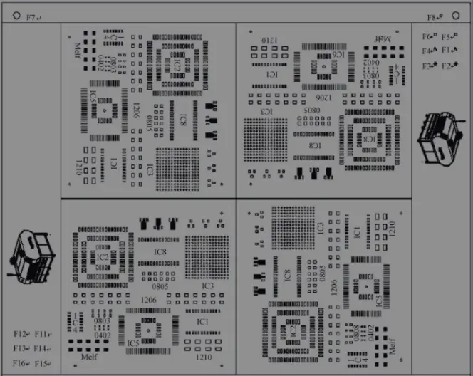
After all assembly work, including software assembly and machine calibration, is completed, the machine will first peRForm component trial placement. The personnel in charge of machine inspection will first load the trial - placement program into the machine, install the feeder and components for trial placement onto the machine, and then run the machine to trial - place components to verify the various functions of the machine. The products for trial placement include some passive and active components, such as 0402, 0603, 0805, 1206, SOT23, SOT89, PLC20, SO24, QFP100, and BGA225 (as shown in the figure below), which can test all functions of the machine.
(2) Dry - Cycle Operation
The machine runs in the dry - cycle mode, and the same program as that used for component trial placement can be adopted. The dry - cycle operation needs to last for at least 40 hours without interruption to ensure the stability of the machine's mechanical and electrical components.
(3) Component Placement Trim
When the machine is calibrated, only the hardware of the machine is checked and corrected, such as the relative positions between the placement axes, the bottom - view camera, and the top - view camera, as well as the magnification, focal length, and light brightness of each camera. However, there is still a certain deviation between the actual position of multiple component placements and the set position in terms of the comprehensive average value. Component placement trim can correct the comprehensive deviation of each placement axis of the placement head, further improving the placement accuracy and capability of the machine, so as to achieve long - term stability of the surface - mount component placement performance.
The general method of component placement trim is to place some standard components. Each placement axis places two components in each of the four placement directions (0°, 90°, 180°, and 270°). Then, the position of each placed component is detected through the bottom - view camera of the machine or a coordinate measuring machine (CMM). The comprehensive deviation of each placement axis in each direction is calculated and then compensated into the parameters of the placement axis.
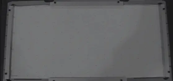
To minimize the influencing factors of the Circuit Board and components, a glass substrate is generally used as the circuit board. The length and width of this glass substrate are 400mm×200mm. The four sides and the back are reinforced with metal to prevent breakage. Some fixed dots are engraved on the glass substrate as calibration and reference datum points (as shown in the figure below).
When used for the placement trim of a multi - functional chip mounter, a glass standard piece equivalent to QFP100 (Pitch = 0.5mm) is used as the component. There is one datum point on each of the four sides of the glass standard piece for identifying the placement position (as shown in Figure 1 below). The glass substrate will be pre - pasted with double - sided tape. If the placement head has 7 placement axes and each placement axis places two components in each of the four directions, then a total of 56 components will be placed (as shown in Figure 2 below).
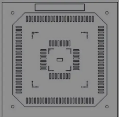
Figure 1: QFP100 Glass Standard Component
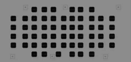
Figure 2: Distribution of QFP100 Components for Placement Trim
When used for the placement trim of a high - speed chip mounter, a well - shaped 0201 standard component is used. The glass substrate will be pre - pasted with double - sided tape. If the placement head has 30 placement axes and each placement axis places two components in each of the four directions, then a total of 240 components will be placed (as shown in the figure below).

After the standard components are placed, run the placement inspection program and specify the configuration of the chip mounter and the model of the standard components. The bottom - view camera of the machine will first identify the 6 datum points on the glass substrate to determine the position of the glass substrate, and then identify the two diagonal datum points on each glass standard piece or the diagonals of the 0201 components. By calculating the positions of the two points on each standard component, the placement position deviation in the X and Y directions and the angular deviation of this standard component can be obtained, as shown in the figure below.
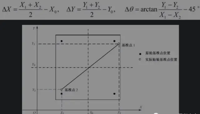
For the same placement axis, the average value of the deviations of the two standard components placed in the same direction is the deviation of this placement axis in this direction. After the positions of all standard components are inspected, the software will automatically calculate and compensate the deviations of each placement axis into the parameters of the placement axis.