 PCB
PCB FPC
FPC Rigid-Flex
 FR-4
FR-4 HDI PCB
 Rogers High-Frequency Board
 PTFE Teflon High-Frequency Board
 Aluminum
 Copper Core
 PCB Assembly
 LED light PCBA
 Memory PCBA
 Power Supply PCBA
 New Energey PCBA
 Communication PCBA
 Industrial Control PCBA
 Medical Equipment PCBA
 Testing Service
 PCBA Testing Service
 Certification Application
 RoHS Certification Application
 REACH Certification Application
 CE Certification Application
 FCC Certification Application
 CQC Certification Application
 UL Certification Application
 Transformers, Inductors
 High Frequency Transformers
 Low Frequency Transformers
 High Power Transformers
 Conversion Transformers
 Sealed Transformers
 Ring Transformers
 Inductors
 Wires,Cables Customized
 Network Cables
 Power Cords
 Antenna Cables
 Coaxial Cables
 Net Position Indicator
 Solar AIS net position indicator
 Capacitors
 Connectors
 Diodes
 Embedded Processors & Controllers
 Digital Signal Processors (DSP/DSC)
 Microcontrollers (MCU/MPU/SOC)
 Programmable Logic Device(CPLD/FPGA)
 Communication Modules/IoT
 Resistors
 Through Hole Resistors
 Resistor Networks, Arrays
 Potentiometers,Variable Resistors
 Aluminum Case,Porcelain Tube Resistance
 Current Sense Resistors,Shunt Resistors
 Switches
 Transistors
 Power Modules
 Isolated Power Modules
 AC-DC Power Modules
 DC-AC Module(Inverter)
 RF and Wireless
Comprehensive Design Guide for Meeting IEC 60601-1 Leakage Current Limits in Medical PCB Certification
(Full-process Control for Type B/BF/CF Equipment)
I. Core Requirements of IEC 60601-1
-
Leakage Current Types & Limits
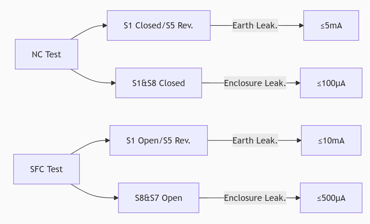
Type Normal Cond. (NC) Single Fault Cond. (SFC) ApplICation Scope Earth Leakage 5mA 10mA All medical equipment Enclosure Leak. 100μA 500μA Metal enclosure/parts Patient Leak. 100μA (B/BF) 500μA (B/BF) Non-cardiac applied parts Patient Leak. 10μA (CF) 50μA (CF) Cardiac-connected parts Key Notes:
-
Even grounded metal enclosures must meet ≤100μA enclosure leakage (NC), not lenient IT limits (5000μA).
-
CF-type requires strictest limits as 10μA may cause ventricular fibrillation.
-
-
Protection Methods
-
MOOPs (Operator Protection): ≥1 layer (e.g., basic insulation).
-
MOPPs (Patient Protection): BF/CF types need 2 layers (e.g., double/reinforced insulation).
-
Example: BF equipment requires 4000VAC/2×MOPP for input-output and 1500VAC/1×MOPP for output-ground.
-
-
II. Critical Pcb Design Technologies
-
Isolation Architecture
-
Reinforced Insulation:
-
Primary-secondary: Creepage ≥8mm (250V), using dual isolation (e.g., polyimide+FR4).
-
Isolation capacitance: <10pF (e.g., planar transformers or low-coupling DC-DC modules like MEAN WELL G-series).
-
-
Floating Ground Design:
-
BF/CF applied parts fully isolated via opto/magnetic couplers, spacing ≥5mm to ground planes.
-
-
-
Routing & Stackup Rules
Parameter Type B Type BF/CF Implementation Signal-Gnd Space ≥2.5mm ≥4.0mm Guard traces with via fencing Power Split Gap ≥0.5mm ≥1.0mm Ceramic-filled isolation slots Edge-HV Trace Dist. ≥3mm ≥6mm GND via array @ board edge (pitch≤3mm) -
Filtering & Shielding
-
Common-mode Filters: At input stage (e.g., π-filter with >40dB@1MHz attenuation).
-
Local Shielding: Mu-metal shields over sensitive zones, directly connected to protective earth.
-
III. Material & Process Controls
-
Substrate & Coating
-
High-CTI Laminates: CTI≥600 (e.g., Rogers 4350B).
-
Conformal Coating: 20-50μm thickness, salt spray test ≥500hrs.
-
Dielectric Layers: Ceramic-filled PTFE (ε_r=3.0, Df<0.001).
-
-
Manufacturing Specs
-
Copper Thickness Tol.: ±2μm .
-
Drilling Accuracy: Mechanical drill offset ≤±5μm; laser microvia ≤±3μm.
-
Soldering: Water-free flux to prevent ionic leakage.
-
IV. Verification Testing & Fault Simulation
-
Leakage Test Flow
-
Equipment:
-
Medical safety tester (e.g., GMC-I SECULIFE ST PRO) with ±1μA accuracy.
-
Test voltage: 264VAC/60Hz (worst case).
-
-
Insulation Strength Validation
-
Withstand Test: 4000VAC/60s for input-output (BF/CF types), leakage <1mA.
-
Defibrillation Test: 5kV peak pulse for CF-type equipment.
-
V. Case Study & Data
Cardiac Monitor (CF-Type)
-
Challenge: Patient leads directly contact heart (≤10μA leakage).
-
Solution:
-
Power path: AC/DC (4000VAC) → Medical DC-DC (MEAN WELL H-series, <2μA patient leakage).
-
Signal path: Reinforced optocouplers (isolation cap. 0.5pF).
-
-
Test Data:
Test Item Limit Result Patient Leak. (NC) 10μA 1.8μA Enclosure Leak. (SFC) 500μA 85μA Isolation Voltage 4000VAC 4200VAC
Design Specs & Certification Keys
| Item | Target | Standard |
|---|---|---|
| Creepage (I/O) | ≥8mm | IPC-6012DA Class 3 |
| Board Leakage | ≤50% of limit | IEC 60601-1 3rd Ed. |
| Documentation | Full FMEA report | ISO 14971 Risk Mgmt. |